
Update: Before you continue reading, please let me discourage you to use polycarbonate, (as I explain at the end of the post): You will be loosing money for the only reason that the cells and the polycarbonate doesn't have same expansion coefficient and lets the water go through it (very slowly), and all the efforts to avoid this disadvantages will fail miserably.
In this post we will see how to build a photoelectric panel DIY the most economical way, yet it is safe and durable (has to endure 25 years). As we shall see, the difficulty of manufacturing is very high, so I recommend it only for the handyman ;). In addition the process is long, but very satisfying if you like the "do it yourself" and are fascinated photovoltaic panels.
I have seen many examples in Internet short - lived home panels , some prepared with wooden frame , I doubt that last more than ten years, or in sealed with silicone tight box (so that moisture comes but then condenses inside unable to leave quickly, corroding cells), whereby the potential savings to the panel in a home goes for the short duration of efficiently it.As discussed in the previous post , my intention was to use polycarbonate, three times it economical than glass, plus much safer and lightweight whose only problem is that dilates 3 times more than glass, and has a light output somewhat lower than the glass (and falling further to whiten with the sun), but stays within a reasonable range during the first 30 years, which is what interests us.
To fasten the solar cells, I have sought more easily and economically; unused support or back cover, but linking them directly to the polycarbonate, and thus kill several birds with one stone :
- Reduces material costs,
- Quicken the panel,
- Avoid possible accumulation of moisture and / or water, as the polycarbonate is not totally impermeable (no plastic is, unless a barrier metal), so it is desirable that no gaps where moist air can accumulate.
- It allows some light to pass between the cells, so that the bottom remains partially illuminated.
- Cells give one the more "fresh" are higher performance; per ° C above 25, panel lose 0.5% efficiency. If we let the rear "air" only with a protective coating (paint, epoxy or silicone), will be best refrigerarán, last longer and give more electricity.
In addition to being glued to the plastic cells, no air pockets barely possible eliminate corrosion problems in the cells by condensation.
Note: That was my intention, but as we shall seethe end, if you join me in this beloved adventure reader will see that attach the cells to polycarbonate is not the best option, but it's better separate leave, so that the plastic dilate freely and heat cells not pass directly thereto . You learn from everything. However, we will detail the procedure used in case you want to use glass as this technical solution itself that would in case of using glass as having the same dilatation cells themselves (the endtheare but you wafers very fine crystalline silicon).
The only problem that this configuration may have a failure to put back cover and use polycarbonate, is that it is less strong against wind gusts (although I used iron colorless transparent polycarbonate of 5 mm. To strengthen it ), so there I install it so that the wind can not affect him violently ; for example putting totally glued to the smooth surface of the roof or wall, without gap behind where the wind can sneak and "pry" pulling it as being anchored polycarbonate in few points, wind stress> 50 kms / nr may be overkill coming from the area of the anchors. We can also avoid this problem by placing it in an area protected from wind,
The great discovery was the neutral silicone , as we saw in the previous post; It allows us a lot of play thanks to its UV resistance, high transparency, good adhesion on all types of materials, economical and easy to use.
It would have been ideal to use transparent liquid silicone glue (although it is no longer necessary as we shall see), but I have not found anywhere, I found liquid type Rubson to waterproof roofs but are colored. Transparent only in cartridge format and quite dense.
The silicone layer must be sufficient to stress the polycarbonate delay does not directly affect the cells, but in the silicone cushion . I calculated eye might be a layer of 2.3 mm,
Buying the polycarbonate sheet
Plates 5 mm. PC's have stores (Plasinco eg.) in plate format 3050 x 2050 mm. which can then supply cut into the format you want.Note: I have chosen to 5 mm. thickness for added stiffness, but 4 mm. no big difference,addition, as discussed below, we have more constructive options ; We could have opted for a plate of 3 mm. and another 2 mm. as a back cover, in Whereby cells will "float" together with silicone dots and the rear plate also connected to multiple points of silicone to the faceplate; I think now is the most durable and tough choice , and so I will do in the next panel to within a month.A whole plate costs 270 euros, and to seize materials, have tried to make the panel as large as possible looking for the balance between overall size and weight , so I opted to buy midplane (1525 x 2050) cut in two to make two panels 1525 x 1025 mm.
With that size gives me to place 5 rows x 9 columns 156x156 mm cell; 45 cells in series produces 0,56V each give me maximum total 25 volts each panel, which will connect in parallel using a diode double schottky with common positive .
Note: We can make the configuration of rows x columns you better come to us for our project , we can always leaveleast 5 mm. betweencells to make connections, and trying toall panels that go tosame micro-inverter have similar voltage (even of different power). There could also be put 6 rows x 8 columns, but there was no room at the extreme sides for planned expansion of polycarbonate.As the Chinese investor who've bought I accept up to 28V input, no problem:


Preparing the frame
For fastening of polycarbonate sheet have to prepare a framework or frame of the required size, in any material that can withstand 30 years outdoors without significantly deteriorate. Ideally the same size or 1 cm. smaller, so that the protruding polycarbonate and protect it from the rain.I have recycled a square tube, leaving a gap between the sensor and the upper berths to separate a little from the wall, as shown in the sketch.
 |
| Sketch frame and panel with slit for dilation and wall tie |

Using a square and a large smooth surface presented slats ; subject and punteamos with plaque size. You can use wood, but do not recommend it because it is rapidly deteriorating weather.

We finished welds and we have to be something like this. Then I applied paint style forging in the welded areas and which were most exposed to corrosion, this painting carries metal particles and is very good corrosion, very durable with only give a hand.
In the center lack of placing a reinforcement , which fails to end to facilitate placement of the photovoltaic cells.

As indicated in the previous drawings, to attach the plate to the support allowing it to be resized freely we prepare oblong holes in the direction of expansion . In areas where much space is reinforce the attachment flanges, as being plastic allow some movement and are very durable (10 years without significant deterioration).
I have prepared a template for tearing holes, I will use to mark their position and then finish them with the drill bit and drill:
 |
| Template torn 8mm. x 2.5 cm long |
For this I used large washers 25 mm diameter rubber. Therebelow I will place pieces of polycarbonate of 1.5 mm. so that it can slide (gum would remain engaged, and also deteriorates).


The tapping screws I used are 8 mm., Just pass through the washer. You can also use a slightly smaller.

Once dry paint the panel put in place a presentation subject with jaws.

And proceed to the marking torn, and with an HSS drill 8 mm. polycarbonate drilled and the top metal, without traverse . If the screw-tapping was chosen smaller, we would have to drill with a drill 1 mm. smaller than the inner diameter of the screw thread.

It is very important to make holes in the innermost part possible to leave enough plate material on the sides ; 2 cms. It is more than enough, to make it strong and not break too easily.

To finish cutting torn'll use a sharp drill bit that has good lateral cut, and holding the template, we help the drill to continue tearing,

also we will tear slightly outward, so that the panel also hold contractions possible frost, and not screw the latching break where. It is a delicate operation that needs to be done with skill and patience.

In my case, as the screws are very long, they moored on the other side, so I finish through the tube with a 6 mm drill. and then put the screws with washers and separator polycarbonate, but not too tight, leaving half mm. about slack to permit free movement of the plate .
To fix them, as they are lazy, I have given them a spot weld on the other side and I cut.

Placing solar cells on the plate
For this first remove the protective film of the inside plate; thanks to the same panel has been preserved without any chafe (remember that it is very easy to scratch):

It's time to mark lines that will guide us to place the cells. Using a plastic the same size as a guide check the distances; We have to consider leaving at least 2 cms. at each end for the dilations of the panel, and between cell and cell minimum 4 mm. to facilitate connections.

Hacemos unas marcas con las divisiones necesarias, e improvisando una regla marcamos con el bolígrafo o rotulador que se pueda eliminar fácilmente una línea discontinua.

Colocando las células
Una vez que tenemos las células fotoeléctricas preparadas con la pista soldada en su lado negativo, con la longitud suficiente para unirlas después al lado positivo en su unión en serie unas con otras, las vamos a ir poniendo sobre el policarbonato.
No explicaré aquí cómo se sueldan, pues hay numerosos vídeos en internet, y tan sólo necesitamos un bote de flux, pistas de cobre estañadas, y un soldador de 60W mínimo con una punta con una zona de la anchura de la pista, y mucha maña y paciencia.
Atención: Las células son obleas de cristal sumamente frágiles, hay que manejarlas con mucho cuidado. No os preocupéis, porque aunque en un principio os cueste, enseguida os acostumbraréis a manejarlas como si fueran discos de CD extremadamente frágiles. ¿He dicho frágiles? Frágiles no, lo siguiente ;).
 |
| Celulas policristalinas 156x156 mm de 14,4% de eficiencia y 3,5W de potencia adquiridas en Ebay |
Colocamos las celulas a presentación para ver qué espacio hemos de dejar entre ellas, ya que iré colocando una a una sobre un colchón de silicona neutra.

Empezamos el proceso en el lado donde van a ir las pistas sueltas para que éstas no nos estorben según vayamos colocando células. Primero echamos un cordón de silicona suficiente del tamaño de la célula.

I smoothed with a spatula trying to leave the same thickness throughout the frame:

And then we carefully cell, pressing them against the silicone. So we must use a smooth surface of the cell size, with a thin rubber on the side that touches the cell to fit and tighten carefully, to reduce air pockets. (However this is not necessary if you use another more correct than this method and we will see in the next post ).
Si oímos un crujido, es que la célula se ha agrietado o roto. Ésto no supone un problema grave siempre y cuando no quede ningún trozo de la célula separada del resto. Y aunque así fuera no reduce la capacidad de las demás células. El problema puede venir si la rotura afecta a la zona de las pistas. En definitiva: Si rompes una célula y la grieta se puede ver a simple vista, es mejor cambiarla.
El hecho de separar la célula del policarbonato con silicona nos va a permitir luego soldarlas con facilidad una vez la silicona esté seca.
Como veremos en la entrada siguiente, no es conveniente hacer una capa de silicona, sino que es mejor aplicarle una finísima capa de protección directamente a la célula en el lado de contacto con el policarbonato, para proteger, y una vez seca colocarla en su sitio, con un cordón de silicona sólo por el contorno para sujetarla y que quede flotando sobre el policarbonato (antes soldarlas usando un cuadrado de cristal del tamaño de la célula para aislar del policarbonato); os lo explicaré mejor en la siguiente entrada con un vídeo. De esta forma evitaremos los problemas relacionados con la dilatación, mejoraremos la transferencia lumínica y gastaremos menos material, facilitando a su vez el posible cambio de una célula averiada.
But you elijáis you elijáis materials, the construction process of a panel is similar; we placing the cells with heads of each row to a different side, and next to the opposite side to then join them easily in series (typically 36 cells, put 45):

In the pictures below you can see how they look.
 |
| When I finished I left over a quarter of a cartridge silicone so I applied on the sides of two rows. |
 |
| You can see that the cells are placed zigzag by |
Tracks welding cells
The next step is finished soldering the cells together . We need a powerful 60W soldering iron, and about 50 mts roll track 100 cells 156x156 mm. tinned copper 2mm. width of good quality.

We verified that the tracks are well in place. The gray side is the positive part of the cells, while the side that faces the sun is the N (negative) semiconductor.

As you see in the next image, given the expansion of the polycarbonate is very important to leave a bent portion in the tracks between the cells so that they can freely stretch and shrink about 5 mm.
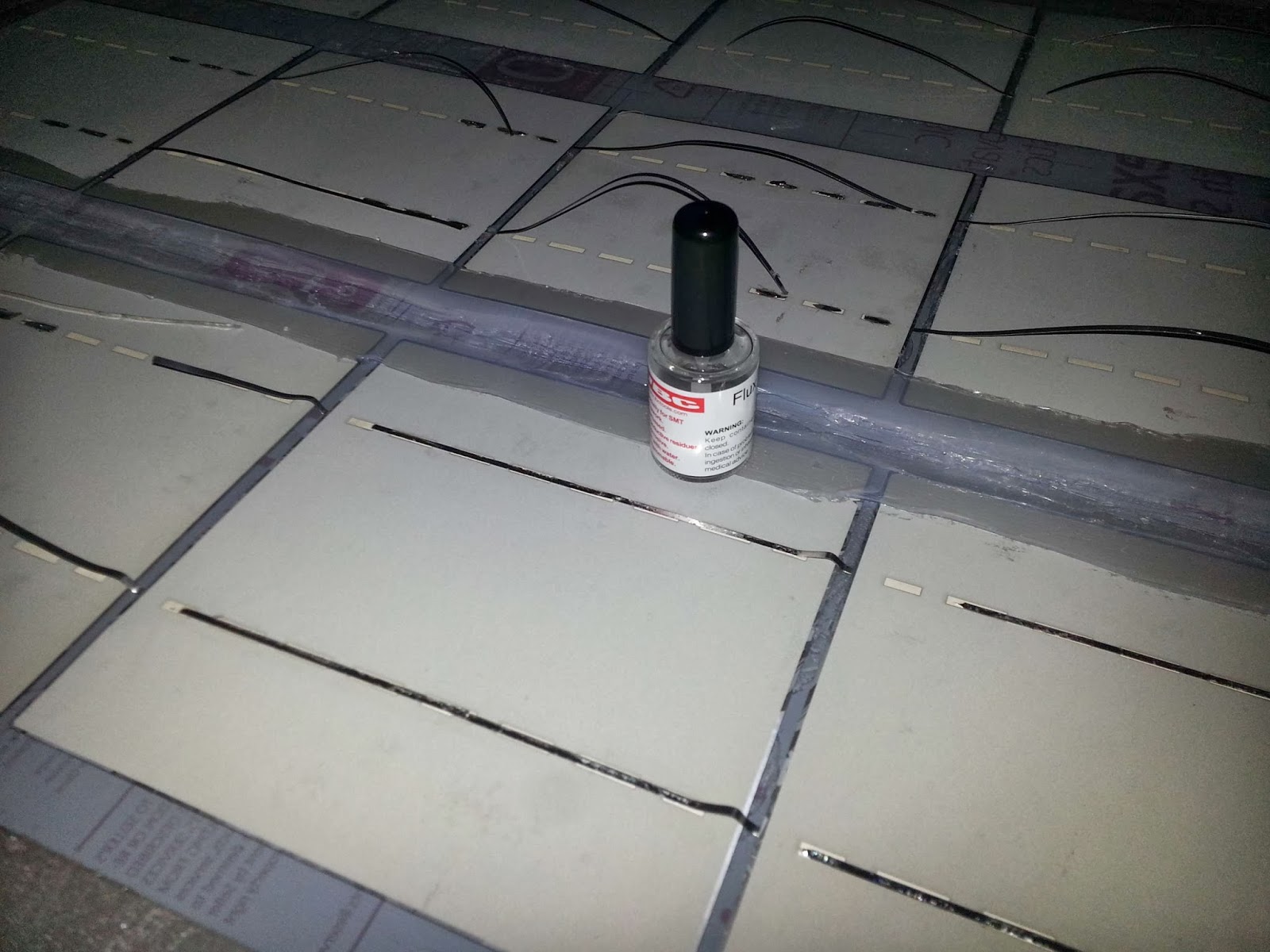
Once prepared, we can apply liquid flux or pencil brush (without welding is very difficult, since it is necessary to remove the oxide layer of conductive thin layer):

We spent the welder holding the track on your site slowly letting the cell tin melts. A single pot of 15 ml flux. I will come to prepare 10 solar panels as this . I bought on Ebay for € 5 + postage.
If you want to avoid having to remove any of the cells after soldering, it is highly recommended that prove the tester before bonding ; in my case one of them, I do not know for what reason, I was very low resistance, only 5 ohms, indicating a clear short (perhaps damaged when welding the track on the other side) while normal is between 200 ohms and 1 K, depending on the light incident on them (the brighter, lower resistance).
 |
| Appearance gap after starting the cutter damaged cell. |
The thickness and width of the tracks used is sufficient to withstand 300W lossless, so we should not always worry that the welds are well done.
 |
| Detail connects two rows in series with double welded wire |
Checking performance panel
And time of truth arrived; We will check panel performance before finishing seal the back of the cells with Brushed silicone.As you can see in the picture looks very good, and although they have been air bags, they do not affect their performance as we shall see.
 |
| Panel sun of February 18, 2014; Note the flanges that I placed to improve the attachment |
I think solar radiation in winter and summer is almost the same, the only difference is the angle of the impinging sunlight (in fact in winter the sun is a little closer). Why panel production fits the theoretical.
 |
| An electronic meter (measures the flow of electricity in both directions) serves ( source ) |
Note: If only one cell is left in the shade , panel production will be 0 watts. And if half of a cell stays in the shade, the production will be half. In this situation the panel does not produce shadow, and the shaded area behaves as a resistance preventing passing electricity consuming production and the rest. So are important blocking diodes , as discussed in a subsequent input when dealing tilt and protection panels.
However the one hour in the sun, the problems started . As shown in the figure below, 3 cells that were already weakened by microcracks to place them , they could not stand the strain and crack are finished (you can see the cracks illuminated):

Carefully examining said cells, we see the severity of the case. When removing the panel temperature was 35 ° C polycarbonate, and about 45 cells. If this has happened to these winter temperatures, I can not imagine what will happen in summer .
 |
| Cracks in cells: When cooled hardly appreciated |
And not only that, but the downside being attached to polycarbonate, the same electrically loaded, attracting pollen particles in the air that had been statically charged by the sun . in one hour the presence of pollen was quite evident. Possible solution to this unexpected? Maybe it's because it was isolated from ground (on a wood), and when placing tied to the wall this load deviates naturally.
Given the relative failure of the experiment (I should have tested samples different ways of placing the cells before anything),
02/24/14 Today I retested the panel and continues to 130W in full sun. Since releasing cells is unfeasible without breaking, I'll leave them as they are, and see what happens with the rest in summer; as in 156 mm. measuring cells expands only 1 mm. , You may have just broken that were already weakened. I will install and continue with the other, placing them otherwise on the polycarbonate.In the next post we see how placing separate PC floating, with a thin layer of silicone to protect cells first, and once dry, place them and we subject with a bead of silicone around only by the outline to keep in place and get best sensor performance while reducing work.
update 05/05/2014

In addition, when much heats the sensor, the power delivered is reduced to 20W to separate some of the cells into several pieces. Still it works, but delivers 100W briefly (if the temperature is low).

Sources:
Project photovoltaic panel polycarbonate (Apparently I was not the first;)Encapsulation of photovoltaic panels home
photocell Spanish Wikipedia
Great pleasure reading your post. Its full of information, thanks for sharing.
ReplyDeleteSolar Albuquerque