
As discussed in the previous post, my goals to put a microcontroller programmed with Arduino on electric bike they were:
- With an RGB LED display the charge / status of the battery monitoring one of the (weaker if possible) cells, to avoid surprises of not having enough charge for the trip the next day, showing orange when needed recharging (between 20 and 40%).
- With an accelerometer and a powerful piezoelectric speaker (and a mosfet to activate) we can add an anti-theft alarm, easy disabled with a button hidden from view, which is very handy against foreign's friends.
- And even (this slope time), add light automatic brake using the accelerometer (which changes from low intensity to high intensity when the accelerometer receives a deceleration in the axis of the fly), to keep usage statistics (number of refills, airtime, or adding small OLED display to show instant consumption in Ah with a Hall sensor (such as Allegro ACS75x, etc), battery charging, etc.
So this Christmas I could get down to work, and start to test in a breadboard to get something functional:
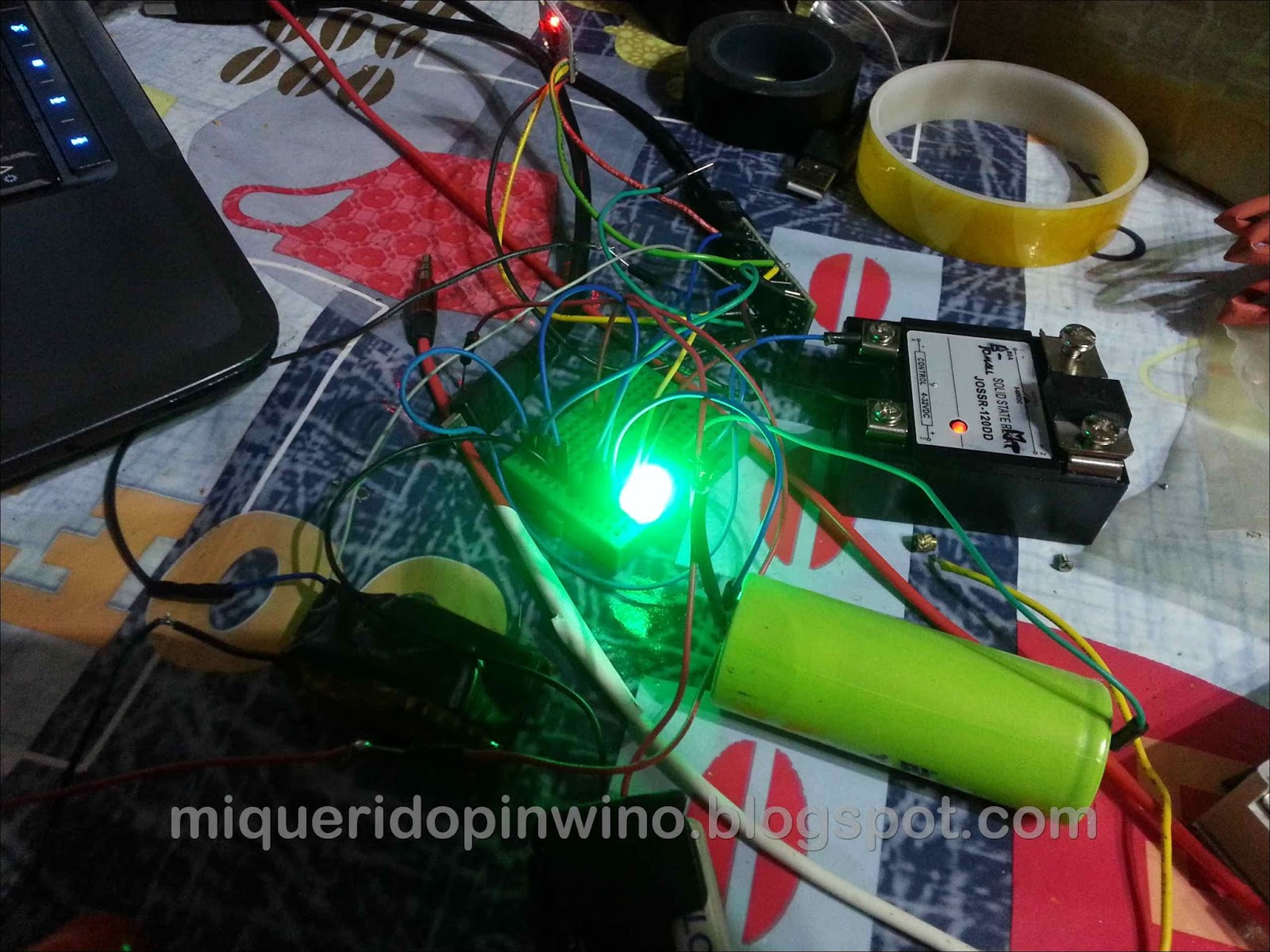
And this is the current version of the program, with LED and accelerometer for alarm ( also on Github ):
 /*  ==================================================================

  Sketch control pensado para un Atmel 328
  Activa un LED RGB según el voltaje y tipo batería (Divisor voltaje)
  Morado sobrecarga, azul 90-100%, verde 50-90%, amarillo del 30 al 40%,
  naranja del 20 al 30%, rojo 10 al 20% y rojo parpadeante por debajo del 10%

  Además, cuando está "dormido" vigila si alguien mueve la vici con el GY-521,
  haciendo sonar la alarma en ese caso.

  Autor: David Losada, basado en trabajos previos de otros autores:
  Parte de código de la referencia rápida del Digispark: http://digistump.com/wiki/digispark/quickref

  Code for the MPU-6050 Accelerometer + Gyro
  By arduino.cc user "Krodal".
  July 2013
  Open Source / Public Domain

  Version: 0.91 bajo licencia GPLv3
  Fecha: enero 2017

  Includes NeoPixel Ring simple sketch code from (c) 2013 Shae Erisson
  released under the GPLv3 license to match the rest of the AdaFruit NeoPixel library

  ==================================================================   */

//#include  //La librería Neopixel ocupa demasiado en el ATtiny; anulo toda la parte de guardado de datos estadísticos
#include  //Para el control del led

//from https://bigdanzblog.wordpress.com/2014/08/10/attiny85-wake-from-sleep-on-pin-state-change-code-example/
#include
//Librerías para dormir al procesador y ahorrar energía cuando no hace nada
#include
#include
#include   //creo que al final no se usa, pero mejor dejarla (el compilador no la incluye si no se usa, por lo que no ocupa)

//******************* A CAMBIAR SEGÚN TU CONFIGURACIÓN ********************************

//Relación de voltaje y estado de carga de la batería; se puede agregar para cualquier tipo de batería, siempre teniendo en cuenta que estaremos comprobando sólo una celda de hasta 5V
//por lo que es imprescindible utilizar un BMS de equilibrado de celdas en la carga para evitar problemas con las celdas no monitorizadas
//Descomentamos el tipo de batería que queramos utilizar
//(VALORES %: 1%,8%,20%,30%,40%,90%,100%)
const double mVoltCarga[7] = {2.75, 3.10, 3.17, 3.198, 3.22, 3.4, 3.6}; //tabla de relación de voltajes y carga de LIFEPO  (recomendado calibrar (más abajo se indica), por la pequeña diferencia entre estados)
//const double mVoltCarga[7]={3,3.2,3.3,3.6,3.65,4.05,4.2}; //tabla de relación de voltajes y carga de LiCo y LiPo
#define ajusteVolt  0.03 //Voltaje de calibración según el chip

#define luminLED    140 //De 20 a 255, el valor de luminosidad máxima según el LED (para ahorro de energía y duración del LED recomendado valores <150 -40="" -512="" -="" 0="" 0x40="" 0x68.="" 0x6b="" 0x75="" 10="" 13="" 16-bits.="" 1="" 20="" 2="" 30="" 340="" 35="" 3="" 4="" 500="" 5="" 7="" 9-axis="" a="" accuracy="" aceleraci="" activa="" activar="" activarlo="" adafruit_neopixel="" al="" alarma="" alida="" all="" alores="" alquien="" an-mpu-6000evb.pdf="" anal="" and="" anterior="" anteriores="" antirrobo.="" anular="" apaga="" apagar="" ara="" arduino="" are="" at="" attiny85="" b="" baje="" bater="" bici="" board="" boolean="" byte="" celsius="" change="" color="" comprobaci="" comprobado="" comprobar="" comunicaci="" con="" conectados="" conectarlo="" config="" configuraci="" connected="" contador="0;" contalarma="resetAlarmaSeg;" cr="" crudo="" cuando="" datos="" de="" debajo="" define="" definiciones="" degrees.="" degrees="" del="" desconectada="" desconectamos="" desconectar="" descriptions="" desde="" digital="" documentation="" documents:="" double="" e="" efinici="" egunda="" ejecute="" el="" electr="" en="" encender="" encendido="true;" entradas="" equipo="" ero="" error="" es="" espera="" espu="" est="" estim="" estos="" evaluation="" example="" except="" for="" formato="" from="" gicos="" gnd="" guardar="" guide="" ha="" hacerlo="" hasta="" hay="" horas="" how="" http:="" iempo="" ierra="" in="" include="" incorporado="" information="" int0="" intermitentemente="" interruptor="" intpin="" invensense="" ire.h="" is="" it="" l="" la="" las="" led="" ledpin="" library="" lmacenar="" lo="" long="" los="" ltimo="" luces="" manipulando="" many="" map="" mero="" might="" millisinicio="0;" millisvoltaje="0;" minutos="" monitorizaci="" more="" movido="" movimiento="" mpara="" mpu-6050:="" mpu-6050="" muestras="" n="" ndose="" need="" neo_grb="" neo_khz800="" neopixel="" neopixels="" nica="" no="" note="" ntrada="" numpixels="" obtenido="" obtenidos="" older="" oltaje="" on="" onectar="" ontrolamos="" or="" p0="" p1="" p4="" para="" parameter--see="" parpadea="false;" parpadear="" parte="" pasen="" paso="" per="" personalizada="" pin="" pines="" pixels="Adafruit_NeoPixel(NUMPIXELS," pl-9823-f5="" playing-with-the-pl9823-f5-a-breadboardable-neopixel-compatible-led="" pod="" ponemos="" poner="" por="" possible="" power-up="" product="" ps-mpu-6000a.pdf="" puntualmente="" pwm="" que="" raw="" read="" register="" registers="" rel="" relepin="" resetalarmaseg="" resetear="" rgb="" rm-mpu-6000a.pdf="" rojo="" rs-mpu-6000a.pdf="" s="" se="" seg.="" seg="" segundos="" send="" sensibilidad="" sensibilidadaccel="" sensor="" setup="" si="" signals.="" siguiente="" son="" specification="" strandtest="" strips="" superan="" surrealitylabs.com="" tell="" temperature="" that="" the="" these="" third="" tico="" tiempo="" tiempocritica="" tiempoespera="" timeled="0;" to="" toleramos="" transcurrido="" two:="" uando="" umbral="" unsigned="" us="" usamos="" use="" user="" valor="" valores="" value="0;" values.="" veces="" voltaje="" voltajepin="" vuestro="" we="" when="" which="" y="" you="" zero="" zumbador="" zumbpin="">
long accelX = 0; //Para comparar los datos raw con los anteriores
long accelY = 0;
long accelZ = 0;
long accelXAnt = 0;
long accelYAnt = 0;
long accelZAnt = 0;
int alarmaAct = 0; //Contador de movimientos detectados
byte esperaAlarma = tiempoEspera; //Espera x segundos desde que se apaga sin movimiento a activar la alarma
//byte bateriaCriticaSeg=tiempoCritica; //Tiempo de espera con batería baja antes de apagar todo

// The name of the sensor is "MPU-6050".
// For program code, I omit the '-',
// therefor I use the name "MPU6050....".


// Register names according to the datasheet.
// According to the InvenSense document
// "MPU-6000 and MPU-6050 Register Map
// and Descriptions Revision 3.2", there are no registers
// at 0x02 ... 0x18, but according other information
// the registers in that unknown area are for gain
// and offsets.
//
#define MPU6050_AUX_VDDIO          0x01   // R/W
#define MPU6050_SMPLRT_DIV         0x19   // R/W
#define MPU6050_CONFIG             0x1A   // R/W
#define MPU6050_GYRO_CONFIG        0x1B   // R/W
#define MPU6050_ACCEL_CONFIG       0x1C   // R/W
#define MPU6050_FF_THR             0x1D   // R/W
#define MPU6050_FF_DUR             0x1E   // R/W
#define MPU6050_MOT_THR            0x1F   // R/W
#define MPU6050_MOT_DUR            0x20   // R/W
#define MPU6050_ZRMOT_THR          0x21   // R/W
#define MPU6050_ZRMOT_DUR          0x22   // R/W
#define MPU6050_FIFO_EN            0x23   // R/W
#define MPU6050_I2C_MST_CTRL       0x24   // R/W
#define MPU6050_I2C_SLV0_ADDR      0x25   // R/W
#define MPU6050_I2C_SLV0_REG       0x26   // R/W
#define MPU6050_I2C_SLV0_CTRL      0x27   // R/W
#define MPU6050_I2C_SLV1_ADDR      0x28   // R/W
#define MPU6050_I2C_SLV1_REG       0x29   // R/W
#define MPU6050_I2C_SLV1_CTRL      0x2A   // R/W
#define MPU6050_I2C_SLV2_ADDR      0x2B   // R/W
#define MPU6050_I2C_SLV2_REG       0x2C   // R/W
#define MPU6050_I2C_SLV2_CTRL      0x2D   // R/W
#define MPU6050_I2C_SLV3_ADDR      0x2E   // R/W
#define MPU6050_I2C_SLV3_REG       0x2F   // R/W
#define MPU6050_I2C_SLV3_CTRL      0x30   // R/W
#define MPU6050_I2C_SLV4_ADDR      0x31   // R/W
#define MPU6050_I2C_SLV4_REG       0x32   // R/W
#define MPU6050_I2C_SLV4_DO        0x33   // R/W
#define MPU6050_I2C_SLV4_CTRL      0x34   // R/W
#define MPU6050_I2C_SLV4_DI        0x35   // R
#define MPU6050_I2C_MST_STATUS     0x36   // R
#define MPU6050_INT_PIN_CFG        0x37   // R/W
#define MPU6050_INT_ENABLE         0x38   // R/W
#define MPU6050_INT_STATUS         0x3A   // R
#define MPU6050_ACCEL_XOUT_H       0x3B   // R
#define MPU6050_ACCEL_XOUT_L       0x3C   // R
#define MPU6050_ACCEL_YOUT_H       0x3D   // R
#define MPU6050_ACCEL_YOUT_L       0x3E   // R
#define MPU6050_ACCEL_ZOUT_H       0x3F   // R
#define MPU6050_ACCEL_ZOUT_L       0x40   // R
#define MPU6050_TEMP_OUT_H         0x41   // R
#define MPU6050_TEMP_OUT_L         0x42   // R
#define MPU6050_GYRO_XOUT_H        0x43   // R
#define MPU6050_GYRO_XOUT_L        0x44   // R
#define MPU6050_GYRO_YOUT_H        0x45   // R
#define MPU6050_GYRO_YOUT_L        0x46   // R
#define MPU6050_GYRO_ZOUT_H        0x47   // R
#define MPU6050_GYRO_ZOUT_L        0x48   // R
#define MPU6050_EXT_SENS_DATA_00   0x49   // R
#define MPU6050_EXT_SENS_DATA_01   0x4A   // R
#define MPU6050_EXT_SENS_DATA_02   0x4B   // R
#define MPU6050_EXT_SENS_DATA_03   0x4C   // R
#define MPU6050_EXT_SENS_DATA_04   0x4D   // R
#define MPU6050_EXT_SENS_DATA_05   0x4E   // R
#define MPU6050_EXT_SENS_DATA_06   0x4F   // R
#define MPU6050_EXT_SENS_DATA_07   0x50   // R
#define MPU6050_EXT_SENS_DATA_08   0x51   // R
#define MPU6050_EXT_SENS_DATA_09   0x52   // R
#define MPU6050_EXT_SENS_DATA_10   0x53   // R
#define MPU6050_EXT_SENS_DATA_11   0x54   // R
#define MPU6050_EXT_SENS_DATA_12   0x55   // R
#define MPU6050_EXT_SENS_DATA_13   0x56   // R
#define MPU6050_EXT_SENS_DATA_14   0x57   // R
#define MPU6050_EXT_SENS_DATA_15   0x58   // R
#define MPU6050_EXT_SENS_DATA_16   0x59   // R
#define MPU6050_EXT_SENS_DATA_17   0x5A   // R
#define MPU6050_EXT_SENS_DATA_18   0x5B   // R
#define MPU6050_EXT_SENS_DATA_19   0x5C   // R
#define MPU6050_EXT_SENS_DATA_20   0x5D   // R
#define MPU6050_EXT_SENS_DATA_21   0x5E   // R
#define MPU6050_EXT_SENS_DATA_22   0x5F   // R
#define MPU6050_EXT_SENS_DATA_23   0x60   // R
#define MPU6050_MOT_DETECT_STATUS  0x61   // R
#define MPU6050_I2C_SLV0_DO        0x63   // R/W
#define MPU6050_I2C_SLV1_DO        0x64   // R/W
#define MPU6050_I2C_SLV2_DO        0x65   // R/W
#define MPU6050_I2C_SLV3_DO        0x66   // R/W
#define MPU6050_I2C_MST_DELAY_CTRL 0x67   // R/W
#define MPU6050_SIGNAL_PATH_RESET  0x68   // R/W
#define MPU6050_MOT_DETECT_CTRL    0x69   // R/W
#define MPU6050_USER_CTRL          0x6A   // R/W
#define MPU6050_PWR_MGMT_1         0x6B   // R/W
#define MPU6050_PWR_MGMT_2         0x6C   // R/W
#define MPU6050_FIFO_COUNTH        0x72   // R/W
#define MPU6050_FIFO_COUNTL        0x73   // R/W
#define MPU6050_FIFO_R_W           0x74   // R/W
#define MPU6050_WHO_AM_I           0x75   // R


// Defines for the bits, to be able to change
// between bit number and binary definition.
// By using the bit number, programming the sensor
// is like programming the AVR microcontroller.
// But instead of using "(1< (accelXAnt + sensibilidadAccel) or accelY > (accelYAnt + sensibilidadAccel) or accelZ > (accelZAnt + sensibilidadAccel)) {
    movimiento=true;
    contador=0; //Contador para la cuenta atrás de tiempo para apagarlo
  }
  else {
    contador++;
    movimiento=false;
  }

  //DEBUG
  //    Serial.print("Alarma en: ");
  //    if (accelX>accelXAnt+sensibilidadAccel) {
  //      Serial.println("X");
  //    }
  //    if (accelY>accelYAnt+sensibilidadAccel) {
  //      Serial.println("Y");
  //    }
  //    if (accelZ>accelZAnt+sensibilidadAccel) {
  //      Serial.println("Z");
  //    }
  //    Serial.print(F("accel x,y,z: "));
  //    Serial.print(accelX, DEC);
  //    Serial.print(F(", "));
  //    Serial.print(accelY, DEC);
  //    Serial.print(F(", "));
  //    Serial.print(accelZ, DEC);
  //    Serial.println(F(""));
  //    Serial.println(esperaAlarma);

  //Guardamos valores anteriores
  accelXAnt = accelX;
  accelYAnt = accelY;
  accelZAnt = accelZ;


  //Para velocidad de respuesta; si se detecta activación manual del interruptor, apagamos LED indicador y desconectamos relé
  //El resto del código se ejecutará 1 vez cada 1 segundos.
  //for(int x=1; x<5 --------------------------------------------------------="" -="" 0="" 1.0.1.="" 100="" 1023="" 10="" 10k="" 14="" 1="" 4="" 5="" 5v="" 6="" :="" a="" able="" acar="" accel="" accel_t_gyro="" accel_t_gyro_union="" acceleration="" aceleraci="" activar="" address="" after="" ahorrando="" ahorrar="" ajustevolt="" al="" alarma="" alarmaact="0;" algo="" alguien="" also="" alto="" amos="" amp="" an="" analogread="" and="" apagamos="" apagatodo="" aparcada="" ar="" ara="" arduino="" are="" around="" asamos="" at="" attiny="" ay="" baja="" bajo="" bater="" be="" bici="" black="" boolean="" buffer="" byte.="" byte:="" bytes="" c="" caso="" center="" coge="" coger="" color:="" common="" con="" conectamos="" conectar="" const="" consumption.="" contador="0;" containing="" continue="" control="" convenient="" could="" cpu="" ctivamos="" ctualizamos="" cualquiera="" cuando="" cuenta="" data="" datos="" de="" decimales="" default="" define="" dejar="" del="" delay="" descartar="" desconectamos="" description:="" despierta="" detecci="" detectar="" device.="" digitalread="" digitalwrite="" digo="" disable="" do="" donalmorrissey.blogspot.com.es="" dormido="" dormimos="" dormir="" dos="" double="" doublemap="" dt="" duda="" durante="" ead="" easier="" ecoge="" edit:="" eemos="" ejecute="" ejemplo="" ejes="" el="" else="" en="" enabled="" encendemos="" encendido="true;" enciende="" enciendetodo="" energ="" enter="" enters="" entersleep="" entre="" equipo="" erial.println="" error="));
      //  Serial.println(error,DEC);


      // Swap all high and low bytes.
      // After this, the registers values are swapped,
      // so the structure name like x_accel_l does no
      // longer contain the lower byte.
      uint8_t swap;
      #define SWAP(x,y) swap = x; x = y; y = swap

      SWAP (accel_t_gyro.reg.x_accel_h, accel_t_gyro.reg.x_accel_l);
      SWAP (accel_t_gyro.reg.y_accel_h, accel_t_gyro.reg.y_accel_l);
      SWAP (accel_t_gyro.reg.z_accel_h, accel_t_gyro.reg.z_accel_l);
      SWAP (accel_t_gyro.reg.t_h, accel_t_gyro.reg.t_l);
      SWAP (accel_t_gyro.reg.x_gyro_h, accel_t_gyro.reg.x_gyro_l);
      SWAP (accel_t_gyro.reg.y_gyro_h, accel_t_gyro.reg.y_gyro_l);
      SWAP (accel_t_gyro.reg.z_gyro_h, accel_t_gyro.reg.z_gyro_l);


      // Print the raw acceleration values
      accelX = accel_t_gyro.value.x_accel;
      accelY = accel_t_gyro.value.y_accel;
      accelZ = accel_t_gyro.value.z_accel;
      //MPU6050_write_reg (MPU6050_PWR_MGMT_1, 1); //Volvemos a desactivar para ahorrar energía
}
</code></pre><br><b>The program basically does this</b>: Informs, changing every second the color of an RGB LED, charge of the first cell (without resistance), which is very reliable, for me varied only -0,03V (with the adjustment is 0,03V). And with the accelerometer, checks on the one hand, when it is on, if there is no movement in 5 minutes (configurable parameter), disconnect the relay, turning off the bike and lights. In that state, after 20 seconds activates transistor alarm if no movement (first briefly as a warning, and then intermittently for several minutes). Each time the program is run, to save some energy, we slept the processor and accelerometer for a second.<br><div style=" es="" eseteamos="" espera="" esperaalarma="tiempoEspera;" exactitud="" executed="" externa="" extra="" false="" filter="" first="" font-family:="" font-size:="" for="" from="" function="" gastando="" gy-521="" gyro.="" gyro="" habr="" has="" hay="" here="" high="" hold="" http:="" i2c-bus.="" i2c-bus="" i2c="" i="" if="" imes="" implemented="" in="" in_max="" in_min="" independiente="" int="" interese="" intermitente="" interrupt="" interruptor="" into="" intpin="" ire.available="" is="" isr="" it="" just="" la="" las="" lectura="" lecturas="" led="" lee_mpu6050="" less="" lo="" los="" low.="" low="" luminled="" m="" make="" mantenga="" margen="" media="" medias="" medium="" memoria="" menos="" merece="" milivoltios="" mode.="" movimiento="" mpu-6050.="" mpu-6050="" mpu6050_read="" mpu6050_write="" mpu6050_write_reg="" mpu="" mpu_6050_write="" mpu_6050_write_reg="" muestras="" mueve="" multiple="" mvoltcarga="" n="" name:="" necesitamos="" new="" nimo="" no="" none.="" nos="" not="" nothing.="" now="" nulamos="" number="" o="" ode="" of="" oltaje=");
    Serial.println(value);
    delay(200);

    //Aquí se evalúa el color del led según los valores del voltaje, para evitar que fluctúe se tiene en cuenta
    //qué color tenía antes, y no cambia hasta que haya una variación mayor de 0,02V
    if (value <= mVoltCarga[2] and value > mVoltCarga[1]) { //ROJO; Recargar lo antes posible
      //Si el color no estaba establecido o era el mismo o ha variado suficientemente el voltaje
      if (color == 0  or color == 1 or (color == 2 and value <= mVoltCarga[2] - 0.02)) {
        color = 1;
        pixels.setPixelColor(0, pixels.Color(0, luminLED, 0));
      }
    }
    else if (value <= mVoltCarga[3] && value > mVoltCarga[2]) { //NARANJA; se parece más al rojo
      if (color == 0  or color == 2 or (color == 3 and value <= mVoltCarga[3] - 0.02) or (color == 1 and value > mVoltCarga[2] + 0.02) ) {
        color = 2;
        pixels.setPixelColor(0, pixels.Color(luminLED * 0.3, luminLED * 0.7, luminLED * 0.1)); //Entre el 20 y el 30%; momento de recargar la batería
      }
    }
    else if (value <= mVoltCarga[4] && value > mVoltCarga[3]) { //AMARILLO color 3
      if (color == 0  or color == 3 or (color == 4 and value <= mVoltCarga[4] - 0.02) or (color == 2 and value > mVoltCarga[3] + 0.02) ) {
        color = 3;
        pixels.setPixelColor(0, pixels.Color(luminLED * 0.4, luminLED * 0.5, 0)); //Aconsejable recargar batería
      }
    }
    else if (value <= mVoltCarga[5] && value > mVoltCarga[4]) { //VERDE color 4
      if (color == 0  or color == 4 or (color == 5 and value <= mVoltCarga[5] - 0.02) or (color == 3 and value > mVoltCarga[4] + 0.02) ) {
        color = 4;
        pixels.setPixelColor(0, pixels.Color(luminLED * 0.5, 0, 0)); //Le bajo la intensidad todavía más; al fin y al cabo, siempre estará encendido
      }
    }
    else if (value <= mVoltCarga[6] && value > mVoltCarga[5]) { //AZUL color 5
      if (color == 0 or color == 5 or (color == 6 and value <= mVoltCarga[6] - 0.02) or (color == 4 and value > mVoltCarga[5] + 0.02) ) {
        color = 5;
        pixels.setPixelColor(0, pixels.Color(0, 0, luminLED)); //Se ha sobrecargado; recomendable no llegar al azul para maximizar vida útil
      }
    }
    else  if (value > mVoltCarga[6]) { //>100% VIOLETA 6
      color = 6;
      pixels.setPixelColor(0, pixels.Color(0, luminLED * 0.6, luminLED * 0.75)); //Por encima de lo recomendado; PELIGROSO
    }
    pixels.show(); //Actualizamos el color del led

    //DEBUG
    //Serial.print(" once="" only="" or="" out.="" out_max="" out_min="" p3="" pagamos="" para="" parameter="" parameters:="" parpadearojo="" pasamos="" pdata="" pena="" peripherals.="" pero="" pido="" pin="" pines="" pixels.color="" pixels.setpixelcolor="" pixels.show="" podr="" pointer="" ponemos="" ponerlo="" por="" power="" power_all_enable="" preestablecidas="" procesador="" program="" pull-up="" qu="" que="" quedan="" queremos="" quot="" r="" rabajamos="" raw="" rdenamos="" re-enable="" read.="" read="" real="" recogida="" refiero="" reg="" register.="" register="" relase="" release="" relepin="" resistencia="" return="" returns:="" rojo="" roman="" rutina="" rutinas="" s="" sacar="" salidas="" se="" segundo="" ser="" serial.print="" service.="" set_sleep_mode="" settings="" si="" sigue="" single="" size="" sizeof="" sleep.="" sleep="" sleep_disable="" sleep_enable="" sleep_mode="" sleep_mode_pwr_save="" sleeping-arduino-part-5-wake-up-via.html="" soltar="" stable.="" start="" suficiente="" tambi="" temp="" temperature="" tener="" text-align:="" the="" there="" thing="" third="" this="" tiempo="" tierra="" timed="" timeout="" to="" todo="" todos="" true:="" true="" uint8_t="" un="" una="" use="" used="" uses="" utina="" valores="" value="value" values.="" values="" vect="" very="" viso="" void="" voltaje="" voltajeant=");
    //Serial.println(voltajeAnt);

    //Si detectamos que la bici no se usa durante el tiempo indicado, apagamos todo, hasta que no se pulse en interruptor del P2 no vuelve a continuar
    if (contador > (minutos * 60)) { //Al hacer tres comprobaciones dentro del tiempo marcado, nos aseguramos
      //Ha pasado el tiempo sin uso; apagamos todo
      apagaTodo();
    }

    //si baja del valor de 1% hacemos sonar alarma brevemente y apagamos todo
    //if (value<=mVoltCarga[0]) {
    //  digitalWrite(relePIN,LOW);
    //  for(int x=1; x<20; x++) {
    //    digitalWrite(zumbPIN,HIGH);
    //    delay(100);
    //    digitalWrite(zumbPIN, LOW); //Desactivamos alarma por si quedaba activada
    //    delay(100);
    //  }
    //  apagaTodo();
    //}
  } //**** FIN IF ENCENDIDO
  else { //Está en modo bajo consumo, led APAGADO
      //Comprobamos si hay movimiento
      if (esperaAlarma>0) { //Descontamos tiempo de espera
        esperaAlarma--;
       }

    //Comprobamos la aceleración comparando con datos anteriores; si se superan en sensibilidadAccel, alquien lo está manipulando
    if (movimiento==true) {
      if (esperaAlarma>0) { //Mientras no pase el tiempo de reposo, ignoramos el movimiento
        esperaAlarma=tiempoEspera;
      }
      else {
        alarmaAct++;
        pixels.setPixelColor(0, pixels.Color(0, luminLED, 0));
        pixels.show();
        if (alarmaAct > 2 and alarmaAct <= 6) {
          digitalWrite(relePIN, HIGH);
          for (int x = 0; x < (alarmaAct * 3); x++) { //Intermitencia de zumbador
            digitalWrite(zumbPIN, HIGH);
            delay(100);
            digitalWrite(zumbPIN, LOW);
            delay(140);
            if (x>1) {
              digitalWrite(relePIN, LOW); //Activamos sólo por 0,5 Segundos el relé y luces
            }
          }
        }
      }
    }

    if (alarmaAct > 6) { //Estando la alarma activada se desactiva la espera final, por lo que es constante la alarma
      alarmaAct++;
      digitalWrite(relePIN, HIGH);  //Enciende relé y con ello luces
      for (int x = 0; x < 10; x++) { //Hace sólo 10 veces esta operación, dejando quitar la alarma con el botón
        if (x>4) {
          digitalWrite(relePIN, LOW); //Apaga tras 0,6 segundos (respuesta lenta del foco, hacemos parpadear)
        }
        digitalWrite(zumbPIN, HIGH);
        digitalWrite(relePIN, HIGH); //Encendemos todo intermitentemente
        pixels.setPixelColor(0, pixels.Color(0, luminLED, 0));
        pixels.show();
        delay(50);
        digitalWrite(zumbPIN, LOW);
        pixels.setPixelColor(0, pixels.Color(0, 0, 0));
        pixels.show();
        digitalWrite(relePIN, LOW);
        delay(60);
      }
      if (alarmaAct > 200) { //Para la alarma
        alarmaAct = 0;
      }
    }

    if (alarmaAct==0) { //No hay movimiento, apagamos LED
      pixels.setPixelColor(0, pixels.Color(0, 0, 0));
      pixels.show();
    }
} //Aquí termina el caso en que esté apagado

  //Esto se ejecuta en todos los casos
  if (value > mVoltCarga[0] and value < mVoltCarga[1] and alarmaAct==0) { //si la batería baja demasiado, avisamos
    if (encendido == false) { //No me interesa que pite mientras ando en la bici
      for (int x = 0; x < 2; x++) {
        digitalWrite(zumbPIN, HIGH);
        delay(150);
        digitalWrite(zumbPIN, LOW);
        delay(150);
      }
    }
    if (parpadea == false) {
      pixels.setPixelColor(0, pixels.Color(0, luminLED, 0)); //color rojo
      pixels.show();
      parpadea = true;
    }
    else {
      pixels.setPixelColor(0, pixels.Color(0, 0, 0)); //apagado
      pixels.show();
      parpadea = false;
    }
  }

  //Si alcanza un valor crítico
  if (value < mVoltCarga[0] and value>2 and encendido==true) { //Avisamos del estado de baja batería
    parpadeaRojo();
  }

  if (value < 2 and encendido==true) { //Celda desconectada (interruptor) o batería sin nada de energía
    apagaTodo();
  }
  //Utilizo la EEPROM para valores estadísticos únicamente; se puede eliminar si se considera
  /* DATOS GUARDADOS EN EEPROM *PENDIENTE DE HACER
      0: Horas funcionamiento Arduino
      3: Último voltaje Arduino, para controlar el número de recargas
      7: Contador de recargas de baterías
      11: Contador de viajes/encendidos
      15: Voltaje máximo histórico
      19: Voltaje mínimo histórico
      23:
      27:
      31:

  */

  ////Guardamos las horas de uso en la EEPROM
  //if ((millis()-millisInicio)>3600000) { //Ha pasado una hora
  //  millisInicio=millis();
  //  EEPROM.update(0,EEPROM.readLong(0)+1); //Añadimos una hora al contador
  //  }
  ////Comprobamos valor mínimo y actualizamos
  //if (EEPROM.readLong(19)>value)  {
  //  EEPROM.update(19,value);
  //}
  ////Comprobamos valor máximo y actualizamos
  //if (EEPROM.readLong(15)<value) {
  //  EEPROM.update(15,value);
  //}

  //Si pasa rato sin que la bici se mueva, se resetea contador de movimientos
  if (alarmaAct > 0 and alarmaAct < 7) {
    contAlarma--;
    if (contAlarma == 0) {
      alarmaAct = 0;
      contAlarma = resetAlarmaSeg;
    }
  }
  if (alarmaAct < 7) { //Para dar velocidad de respuesta
    enterSleep(); //Ahorramos batería ya que está el 99% del tiempo " voltajepin="" voltios="" watchdog="" wdt="" when="" while="" will="" wire.begintransmission="" wire.endtransmission="" wire.read="" wire.requestfrom="" with="" wrapper="" write.="" write="" write_reg="" written="" x="" y="" ya="">
Used materials
- Arduino Nano (Atmel 328-16 Mhz), with 30 Ks Free FLASH and 2 Ks SRAM for variables, enough for everything you can think of :
 |
| Pictured with transparent protecting water EPOXI (I deleted the LED ON) |
- PL-9823 RGB LED with integrated micro, much better than a normal LED RGB, because it has many advantages ; we do not need resistors (5V supply and ready), and the blend color is exactly what we want (regulating digitally from 0 to 255 each color) with the Arduino.
 |
| It is fatter than a normal RGB to keep a microcontroller built |
And you can be connected in series to geniuses like this :
These LEDS RGB are the latest advance by integrating the controller on the same chip , so just pass color data we want to indicated to immediately change without resistance to lower the voltage (in a normal RGB chip each Color uses a different resistance).
| Image: Adafruit.com |
I used the library Adafruit Neopixel to handle the indicator, but one is currando faster for projects multiple LEDs.
 |
| We have different heights; F8 8mm and 5mm F5 |
- Accelerometer MPU-6050 (Encapsulated GY-521) with which we detect movements, acceleration, etc. (has to temperature sensor):

- A 0.5A MOSFET N channel unless it is activated with 5V; the typical 2N2222 worth us to activate the speaker will alarm.
- An electronic relay or SSR (Solid State Relay) 80A DC (real):

- A speaker / piezo buzzer , as powerful as possible to discourage burglars:

Installing the LED RGB
I opened the throttle part of Golden Motor electronics; electronics was prepared to 48V so no use to me; 3 wires are used for the Hall sensor throttle (can not use mass accelerator as common ground for referrals that are in the BAC-0281P driver , and end up overheating the sensor, I checked) and the rest for electronics and reverse switch (which I will take to turn on / off the beam and to switch between 3 light intensities), and I used to the LED and hidden on / off the bike in the brief stops microswitch ( and activation of the burglar alarm).
The bike has no ignition key , but use a hidden from view switch to activate / deactivate, and another switch to turn off the voltage reading and avoid unbalancing the first cell when not in use.
I Blew one of the holes to introduce Led PL-9823, then fixing it with epoxy glue , and insulated with heat shrink tubing red once welded connections:

The lid is easy to remove ; They are only two screws to separate the side, which is press - fitted. Needless to release the handle.
And in the next picture with all cables already placed on your site (be careful that the movement does not touch the accelerator or engages in any of them):

The connection of the cables, referred to the Arduino Nano:

And here the nucleus of control: The MPU-6050 connected to the Arduino Nano (above epoxy to protect it from moisture / water that may enter).

To permanently feed and used a voltage regulator that supports up to 40V (with efficient LM2596S) and feeding it to 33V with my pack I can adjustable from 1V to 30V, very accurate, so I put it to 5V and food to the Nano directly 5V line to prevent loss of voltage regulator Nano.
 |
| Voltage regulator carrocero covered with tape exposing only the adjustment screw |
This controller is identical to that used for feeding 3V LED lights , and I hit an aluminum sink to act, only to power the arduino is not necessary to put sink for low power consumption:
 |
| An efficient regulator 3-40V riding a LM2596S with a sink stuck with silicone |
In the next picture is the NANO connected to the bike lie what I program with a change:
I think that is all; the initial scheme (put) speaks for itself, but if you have any questions comentaís.
On the other hand, I use a ceramic 50A slow fuse to protect the pack of batteries of any short:

Substituting one mechanical relay Solid State (semiconductor)
On the other hand, so far used on the bike a mechanical relay 100A and 12V (typically used in vehicles), which activated with a small switch connected to the third cell of the battery (3,3x3 = 9,9V), and occupied enough:
And I used to replace it with an electronic relay , for that to improve the bike.
Now it is not the first time that I use and I speak about this type of electronic relays , its advantages and disadvantages. I used one of them in a car (with bad result for its low quality), but very useful and long - lived if used within its limits.
 |
| The diode drift is the current to the battery in all cases to protect control before long hills. |


But he did not have them, so the moment I will leave with the SSR , and go down without checking how much it will be used and so I try to see how it behaves.
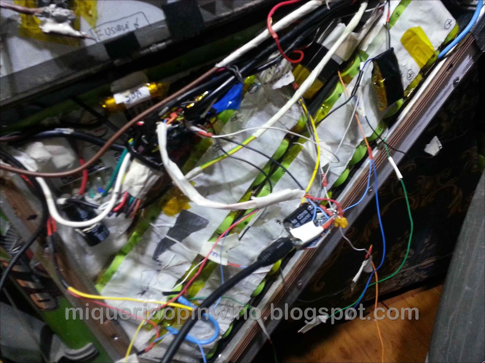
I have also isolated and protected from moisture BMS that I mentioned in the previous entry , applying a generous layer of transparent epoxy two components to electronics:

And this is the final aspect of all the electronics and wiring; I have taken up the free holes for the wires (protecting supporting more amperage with masking tape if the heat softens the insulation) and covering everything with masking tape so that there is no problem:
 |
| At the top next to the fuse 50A voltage regulator supplying seen the Arduino Nano |
For ad. info: Previous tests with ATtiny85
At first I tried to get much of this with a small ATtiny85 ,

 |
but I had no problems because of their limitations , forgetfulness, and was not able to program it to take advantage of a UNO 8 ks memory (plus the burglar alarm was out):

However, as voltage indicator for a single stack, it is most suitable due to its very low consumption if powered by the 5V input; one LiFePo4 cell has between 2.7 and 3.6V, so the Attiny work perfectly, and consuming very little:

and if libraries Low-Power (waking only every second or two to check the voltage) are installed, we leave it in the order of picoAmperes:


 /* ==================================================================
  Sketch control de batería, pensado para su funcionamiento en un Attiny85
  Activa un LED RGB según el voltaje y tipo batería (Divisor voltaje)
  Morado sobrecarga, azul 90-100%, verde 50-90%, amarillo del 30 al 40%,
  naranja del 20 al 30%, rojo 10 al 20% y rojo parpadeante por debajo del 10%
  Autor: David Losada, basado en trabajos previos de otros autores:
  Parte de código de la referencia rápida del Digispark: http://digistump.com/wiki/digispark/quickref
  Version: 0.5 bajo licencia GPLv3
  Fecha: octubre 2016
  Includes NeoPixel Ring simple sketch code from (c) 2013 Shae Erisson
  released under the GPLv3 license to match the rest of the AdaFruit NeoPixel library
  ==================================================================  */
 //#include  //La librería Neopixel ocupa demasiado en el ATtiny; anulo toda la parte de guardado de datos estadísticos
 #include  //Para el control del led
 //from https://bigdanzblog.wordpress.com/2014/08/10/attiny85-wake-from-sleep-on-pin-state-change-code-example/
 #include
 #include  //creo que al final no se usa, pero mejor dejarla (el compilador no la incluye si no se usa, por lo que no ocupa)
 //******************* A CAMBIAR SEGÚN TU CONFIGURACIÓN ********************************
 //Relación de voltaje y estado de carga de la batería; se puede agregar para cualquier tipo de batería, siempre teniendo en cuenta que estaremos comprobando sólo una celda de hasta 5V
 //por lo que es imprescindible utilizar un BMS de equilibrado de celdas en la carga para evitar problemas con las celdas no monitorizadas
 //Descomentamos el tipo de batería que queramos utilizar
 //(VALORES %: 1%,8%,20%,30%,40%,90%,100%)
 const double mVoltCarga[7]={2.8,3.10,3.17,3.198,3.22,3.4,3.6}; //tabla de relación de voltajes y carga de LIFEPO (recomendado calibrar (más abajo se indica), por la pequeña diferencia entre estados)
 //const double mVoltCarga[7]={3,3.2,3.3,3.6,3.65,4.05,4.2}; //tabla de relación de voltajes y carga de LiCo y LiPo
 const byte luminLED=150; //De 20 a 255, el valor de luminosidad máxima según el LED (para ahorro de energía y duración del LED recomendado valores <150 -="" 0="" 12="" 1="" 255="" 2="" 4="" 512="" 5="" 6000="" 6="" 6v="" a="" acar="" acemos="" acer="" activar="" activarlo="" actualizado="" adafruit_neopixel="" ahorrando="" ahorrar="" ajustar="" ajustarlo="" al="" alarma="" alida="" alores="" alto="" amos="" anal="" analog="" analogread="" analogwrite="" and="" anterior="" apagado="" apagar="" aparecer="" ara="" arduino="" asamos="" attiny85="" attiny="" azul="" b="" baje="" bajo="" bater="" bici="" boolean="" borrado="" byte="" bytes="" cada="" calibra="" calibraci="" calibrar="" calibvolt="" change="" chequeo="" cimas="" coge="" coincidiera="" color="" colores="" como="" completo="" comprobaci="" comprobamos="" comprobar="" comunicaci="" con="" conectados="" conectarlo="" connected="" const="" contar="" convierte="" cuando="" cumplir="" d="" datos="" de="" deber="" decimales="" define="" del="" delay="" descartar="" desconectamos="" desconectar="" digital="" digitalwrite="" doble="" dos="" double="" doublemap="" ecoge="" eemos="" eeprom.update="" eeprom="" efinici="" efinir="" egunda="" el="" electr="" en="" encender="" entera="" entradas="" entre="" env="" erde="" erial.begin="" erial.println="" es="" escomentar="" ese="" esetea="" espacio="" espera="" espu="" est="" esto="" estos="" evitando="" exactitud="" example="" final="" for="" from="" funcionan="" gicos="" gnd="" guardar="" guardo="" ha="" hacerlo="" hacerse="" hardware.="" hasta="" have="" hay="" he="" hequeo="" high="" horas="" how="" http:="" i="" iempo="" ierra="" if="" in="" incorporado="" indicar="" indicativo="" information="" inicializado="" inicio="" initializes="" input="" int0="" int="" interferencias="" intermitente="" intermitentemente="" interna="" interruptor="" intpin="" is="" it="" justar="" l="" la="" lanco="" las="" later="" le="" lecturas="" led="" ledpin="" leds="" lee="" library.="" library="" liminar="" lmacenamos="" lmacenar="" lo="" long="" loop="" los="" ltima="" luces="" m="" many="" marcha="" media="" mediante="" medias="" memoria="" merece="" mero="" might="" milisegundos="" milivoltios="" millisinicio="millis();" millisuso="millis();" millisvoltaje="0;" minutos="" mode="" monitorizaci="" more="" motor="" mpara="" muestras="" n="" ncendemos="" necesitamos="" need="" neo_grb="" neo_khz800="" neopixel="" neopixels="" nica="" niciamos="" nimo="" no="" not="" note="" number.="" number="" numpixels="" o="" obtenido="" obtenidos="" older="" oltaje="" on="" onectar="" onemos="" orrado="" ou="" output="" p0="" p1="" p4="" para="" parada="" parameter--see="" parpadea="false;" parpadear="" parte="" pasamos="" paso="" pena="" physical="" pin="" pines="" pinmode="" pixels.begin="" pixels.color="" pixels.setpixelcolor="" pixels.show="" pixels="Adafruit_NeoPixel(NUMPIXELS," pl-9823-f5="" playing-with-the-pl9823-f5-a-breadboardable-neopixel-compatible-led="" poco="" posici="" possible="" preferiblemente="" primer="" primera="" probar="" programa="" pueda="" puede="" puesta="" pullup="" punto="" pwm="" qu="" que="" quitamos="" rabajamos="" raro="" rdenamos="" reactivar="" read="" readlong="" readvcc="" real="" recomendado="" ref.="" refintvolt="1.088;" rel="" relepin="" rellenamos="" reseteado="" resistencia="" rgb="" rojo="" rutina="" s="" saber="" sacar="" se="" seg="" seguidas="" send="" ser="" serial.println="" set="" setmaxallowedwrites="" setmempool="" setup="" si="" signals.="" son="" stablecemos="" strandtest="" strips="" su="" surrealitylabs.com="" tama="" tantas="" tarjeta="" tell="" tendr="" tengo="" terminado="" that="" the="" then="" third="" this="" though="" tiempo="" tiene="" tierra="" timeled="millis();" to="" todos="" transcurrido="" ttiny85="" uardar="" un="" unsigned="" us="" usamos="" usando="" usar="" use="" utilizada="" valor="" valores="" value="int((value-int(value))*100);" values.="" variaci="" variar="" veces="" verde="" vez="" void="" voltaje="" voltajeant="0;" voltigual="false;" voltios="" vuelve="" want="" we="" when="" where="" which="" x="" y="" ya="" you="" zul="" zumbador="" zumbpin=""> 9 pulsos del led)
 //for(int x=0; x.5) { //ROJO PARPADEANTE, SE DAÑA LA BATERÍA; RECARGAR LO ANTES POSIBLE
    color=0;
    if (parpadea==false) {
     pixels.setPixelColor(0, pixels.Color(0,luminLED,0));
     parpadea=true;
    }
    else { pixels.setPixelColor(0, pixels.Color(0,0,0)); //apagado
    parpadea=false;
    }
 }
 else if (value<=mVoltCarga[2] && value>mVoltCarga[1]) { //ROJO; Recargar lo antes posible
    //Si el color no estaba establecido o era el mismo o ha variado suficientemente el voltaje
    if (color==0 or color==1 or (color==2 and value<=mVoltCarga[2]-0.02)) {
     color=1;
     pixels.setPixelColor(0, pixels.Color(0,luminLED,0));
    }
 }
 else if (value<=mVoltCarga[3] && value>mVoltCarga[2]) { //NARANJA; se parece más al rojo
    if (color==0 or color==2 or (color==3 and value<=mVoltCarga[3]-0.02) or (color==1 and value>mVoltCarga[2]+0.02) ) {
     color=2;
     pixels.setPixelColor(0, pixels.Color(luminLED*0.3,luminLED*0.7,luminLED*0.1)); //Entre el 20 y el 30%; momento de recargar la batería
    }
 }
 else if (value<=mVoltCarga[4] && value>mVoltCarga[3]) { //AMARILLO color 3
    if (color==0 or color==3 or (color==4 and value<=mVoltCarga[4]-0.02) or (color==2 and value>mVoltCarga[3]+0.02) ) {
     color=3;
     pixels.setPixelColor(0, pixels.Color(luminLED*0.4,luminLED*0.5,0)); //Aconsejable recargar batería
    }
 }
 else if (value<=mVoltCarga[5] && value>mVoltCarga[4]) {//VERDE color 4
    if (color==0 or color==4 or (color==5 and value<=mVoltCarga[5]-0.02) or (color==3 and value>mVoltCarga[4]+0.02) ) {
     color=4;
     pixels.setPixelColor(0, pixels.Color(luminLED*0.5,0,0)); //Le bajo la intensidad todavía más; al fin y al cabo, siempre estará encendido
    }
 }
 else if (value<=mVoltCarga[6] && value>mVoltCarga[5]) {//AZUL color 5
    if (color==0 or color==5 or (color==6 and value<=mVoltCarga[6]-0.02) or (color==4 and value>mVoltCarga[5]+0.02) ) {
     color=5;
     pixels.setPixelColor(0, pixels.Color(0,0,luminLED)); //Se ha sobrecargado; recomendable no llegar al azul para maximizar vida útil
    }
 }
 else { //>100% VIOLETA 6
    color=6;
    pixels.setPixelColor(0, pixels.Color(0,luminLED*0.6,luminLED*0.75)); //Por encima de lo recomendado; PELIGROSO
 }
 pixels.show(); //Actualizamos el color del led
 //Comprobamos si millis se ha desbordado (tras 50 días)
 if (millisUso>millis()) {
  millisUso=millis();
 }
 if (millisVoltaje>millis()) {
  millisVoltaje=millis();
 }
 //Si detectamos que la bici no se usa durante el tiempo indicado, apagamos todo, hasta que no se pulse en interruptor del P2 no vuelve a continuar
 if ((millis()-millisUso)>=20000*long(minutos)) { //Al hacer tres comprobaciones dentro del tiempo marcado, dividimos entre tres los minutos
  millisUso=millis();
  if (parada==false) {
   parada=true;
   voltajeAnt=value; //Para redondear a 3 dígitos (sólo nos interesa comparar con dos decimales)
  }
  else {
   parada=false;
   if (value<=voltajeAnt-0.01 and value<=voltajeAnt+0.01) {
    voltIgual=true;
    millisVoltaje=millis();
   }
  }
 }
 if (voltIgual==true && (millis()-millisVoltaje)>=20000*long(minutos)) {
   millisVoltaje=millis(); //reseteamos tiempo
   voltIgual=false;
   if (voltajeAnt==value) {
    //En dos chequeos durante el tiempo no ha cambiado voltaje, por lo que dormimos la cpu
    apagaTodo();
   }
 }
 //Para protección de batería
 //Si baja del 4,5% la batería, activamos zumbador hasta que sea del 1% o menor
 if (value<=(mVoltCarga[0]+mVoltCarga[1])/2 && value>=mVoltCarga[0]) {
  if (alarma==false) {
   alarma=true;
   digitalWrite(zumbPIN,HIGH);
  }
  else {
  alarma=false;
  digitalWrite(zumbPIN, LOW);
  }
 }
 //si baja del valor de 1% hacemos sonar alarma brevemente y apagamos todo
 if (value<=mVoltCarga[0]) {
  digitalWrite(relePIN,LOW);
  for(int x=1; x<20 0:="" 11:="" 15:="" 19:="" 23:="" 27:="" 31:="" 3:="" 7:="" activada="" alarma="" apagatodo="" arduino="" as="" attiny85="" bater="" considera="" contador="" controlar="" da="" datos="" de="" del="" delay="" digitalwrite="" eeprom="" el="" eliminar="" en="" encendidos="" esactivamos="" estad="" funcionamiento="" guardados="" hacer="" hist="" horas="" if="" la="" las="" low="" ltimo="" m="" memoria="" mero="" millis="" millisinicio="" n="" nicamente="" nimo="" no="" para="" por="" puede="" puedo="" quedaba="" recargas="" rico="" se="" si="" sticos="" tilizo="" uardamos="" usarlo="" uso="" valores="" viajes="" voltaje="" x="" ximo="" zumbpin="">3600000) { //Ha pasado una hora
 // millisInicio=millis();
 // EEPROM.update(0,EEPROM.readLong(0)+1); //Añadimos una hora al contador
 // }
 ////Comprobamos valor mínimo y actualizamos
 //if (EEPROM.readLong(19)>value) {
 // EEPROM.update(19,value);
 //}
 ////Comprobamos valor máximo y actualizamos
 //if (EEPROM.readLong(15)millis()) { //Cuando pasen 50 dias resetear
   timeLED=millis();
  }
  if ((millis()-timeLED)>2000) {
    analogWrite(ledPIN,100); //enciende LED brevemente indicando funcionamiento
    timeLED=millis();
    delay(50);
    analogWrite(ledPIN,0);
  }
 //Para velocidad de respuesta; si se detecta activación manual del interruptor, ponemos a dormir la bici
 //El resto del código se ejecutará 1,5 veces cada segundo aprox.
 for(int x=1; x<20 -="" 1.1v="" 10k="" 1125300="1.1*1023*1000" 1="" 2="" _bv="" a="" above="" activar="" adc="" adch="" adcl="" adcsra="" admux="_BV(REFS0)" against="" al="" algo="" amos="" amp="" and="" apagamos="" apagatodo="" aqu="" arduino="" as="" attiny="" avcc="" ay="" bit="" bit_is_set="" both="" break="" c="" calculate="" calibraci="" change="" clear="" cli="" code="" con="" conectamos="" conectar="" continuar="" conversion="" cpu="" ctualizamos="" cuando="" cuenta="" de="" defined="" delay="" digitalread="" digitalwrite="" digo="" disable="" dormimos="" dormir="" double="" doublemap="" duda="" ejemplo="" el="" elif="" else="" en="" enable="" endif="" entrada="" entre="" es="" esta="" externa="" first="" for="" gastando="" gimsk="" habr="" hacer="" hay="" he="" high="ADCH;" if="" in="" in_max="" in_min="" independiente="" interna="" internal="" interrupci="" interrupt="" interruptor="" interrupts="" intpin="" isr="" it="" la="" las="" lectura="" led="" lido="" llama="" lo="" locks="" long="" los="" low.="" low="" mantenga="" mcucr="" measurement="" measuring="" mega1280__="" mega2560__="" mega32u4__="" menos="" millivolts="" must="" mv="" n="" necesito="" no="" ocurre="" off="" on="" ormimos="" out_max="" out_min="" p3="" p4="" pagamos="" para="" pb3="" pcmsk="" pero="" pin="" pines="" pixels.color="" pixels.setpixelcolor="" pixels.show="" podr="" ponemos="" ponerlo="" por="" preestablecidas="" preferido="" puede="" pull-up="" que="" quedan="" read="" readvcc="" reference="" referencia="" refiero="" register="" relepin="" replaces="" resistencia="" result="" resultado="" return="" rutina="" rutinas="" s="" salidas="" se="" sei="" ser="" set="" set_sleep_mode="" sets="" settle="" si="" sigue="" sleep="" sleep_cpu="" sleep_disable="" sleep_enable="" sobre="" soltar="" start="" statement="" suficiente="" tener="" teor="" the="" then="" tiempo="" tierra="" tiny24__="" tiny25__="" tiny44__="" tiny45__="" tiny84__="" tiny85__="" to="" todo="" todos="" tras="" turn="" uint8_t="" una="" unlocks="" usar="" utilizar="" variar="" vcc="" vect="" void="" voltaje="" vref="" wait="" while="" x="" y="" ya="">
It was used part of the code reference Digispark for the voltage on the same pin power (with the internal reference of 1.1V). As you have seen, in the end I opted for Nano , riding a Atmel 328 and is compact; we have 30 Ks flash memory available and 2 Ks SRAM, and enough inputs and outputs to do many things :). With these improvements the bike already has everything I wanted to have , now enjoy daily with her! (I hope not having to play their guts in a long season, bufff;)
PS: Thanks honey for your patience!
No comments :
Post a Comment